Ducted Desk Fan
I had a cheap(ish) fan from Amazon that I used a ton- blowing air across the table while I was cutting onions so I wouldn’t tear up, pushing smoke out the window when I was searing meat, keeping me cool while I was working at my desk, etc. It was extremely useful. 3 different fan settings, USB-C rechargeable, a strong clip at its base, and it could tilt and pan as necessary. My only gripe was that around the fan, there was just a cage of injection-molded plastic shrouding the blades. This is the exact fan, to give an idea of what I’m taking about:
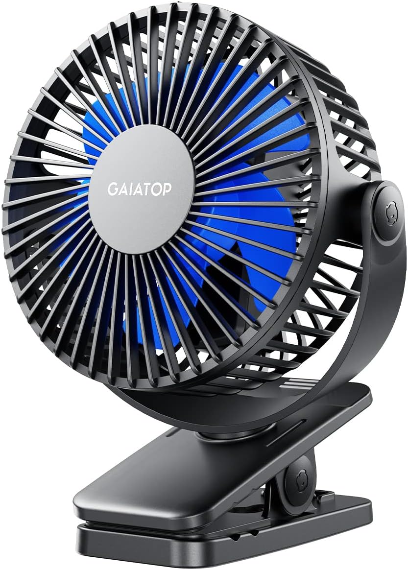
I thought that this fan would go from ‘good’ to ‘great’ if I could keep all of its main functions: USB-C, tilt, pan, etc., and add in the benefits of ducting to improve airflow.
Why ducting, and why isn’t it standard?
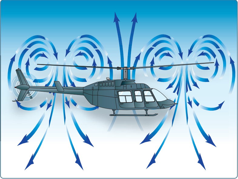
Ducting’s main benefit is in reducing tip vortices. I took a rotordynamics course in grad school, and one of the first things I learned is that one of the primary ways to simplify a rotor is to treat it as an actuator disk, or an infinitely thin, permeable disk that imparts forces on the fluid passing through it. In real life, there’s an effect that pretty much ruins this approximation: tip vortices. One big assumption in the actuator disk theory is that as this infinitely thin disk ‘creates’ a pressure differnetial, the high-pressure air doesn’t ‘leak’ through the disk to the low-pressure side. Tip vortices are the real-life mechanism that let this leakage happen. As the desk fan spins, it creates a pressure differential in the air, via the work mechanism of the rotor. Without some sort of duct to eliminate these tip vortices, the high-pressure air is free to curl around the tip of the blades to the low-pressure side, nerfing efficiency.
My best guess as to why ducting or shrouds like this aren’t standard: expense. It’s a lot more plastic and a lot more annoying an assembly process to deal with a relatively heavy and obstructive shroud, vs a low-material solution like a cage. This all translates into cost for a mass-manufacturer trying to beat out tons of competition across e-commerce. The shroud also adds a non-negligible amount of bulk and heft to the fan, biting into its portable/lightweight selling point.
Design Specifics
Flowpath Design
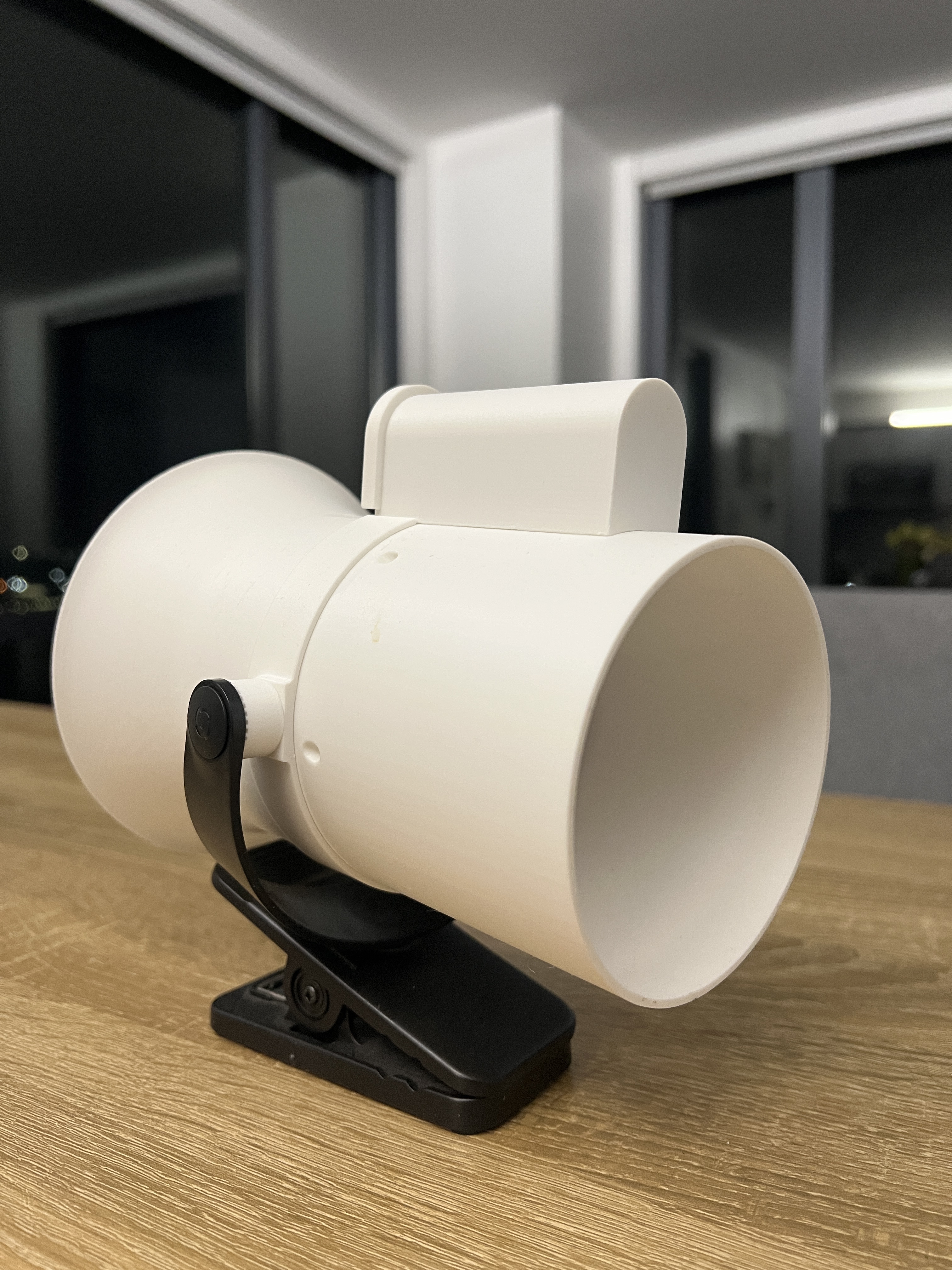
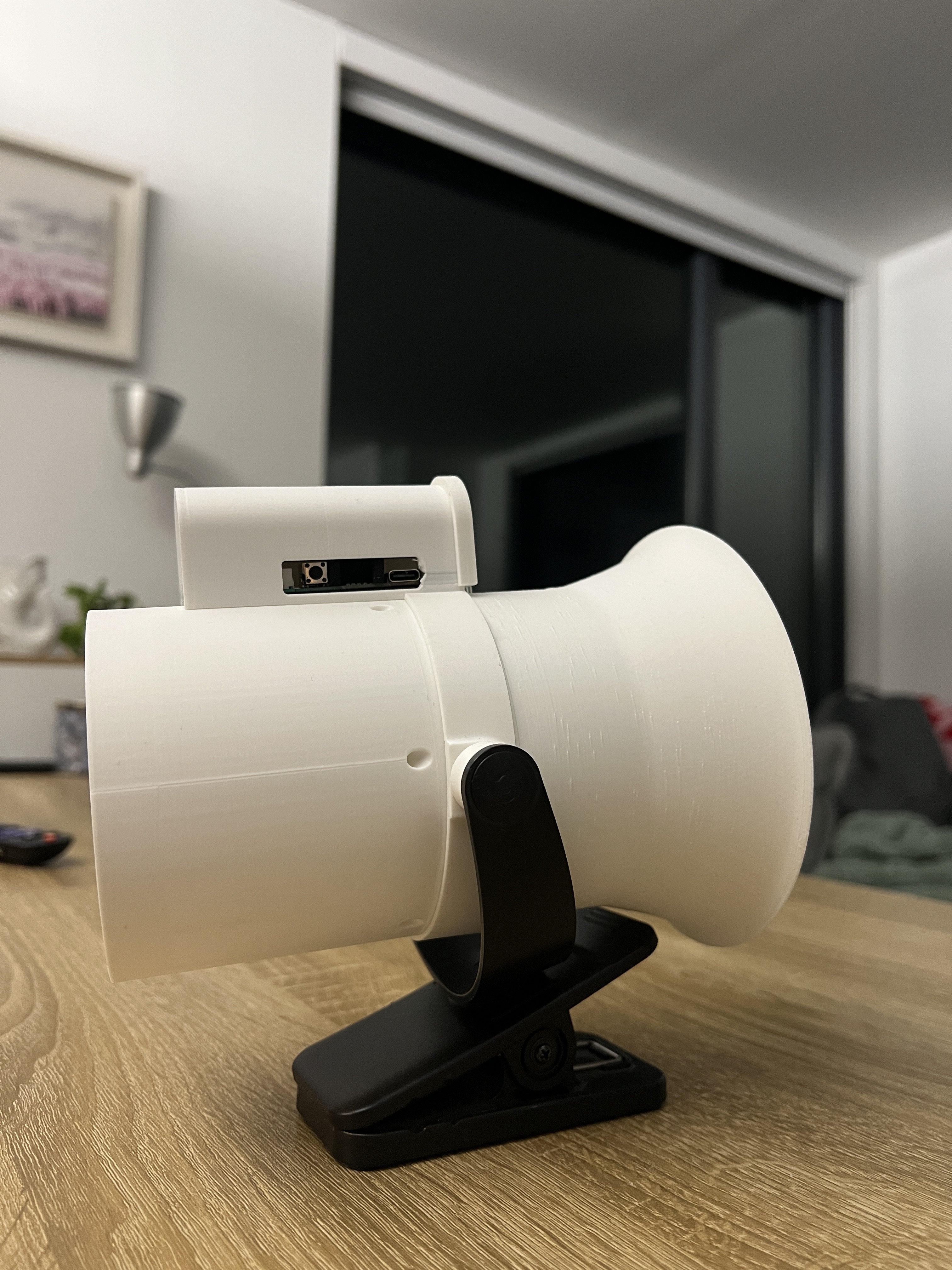
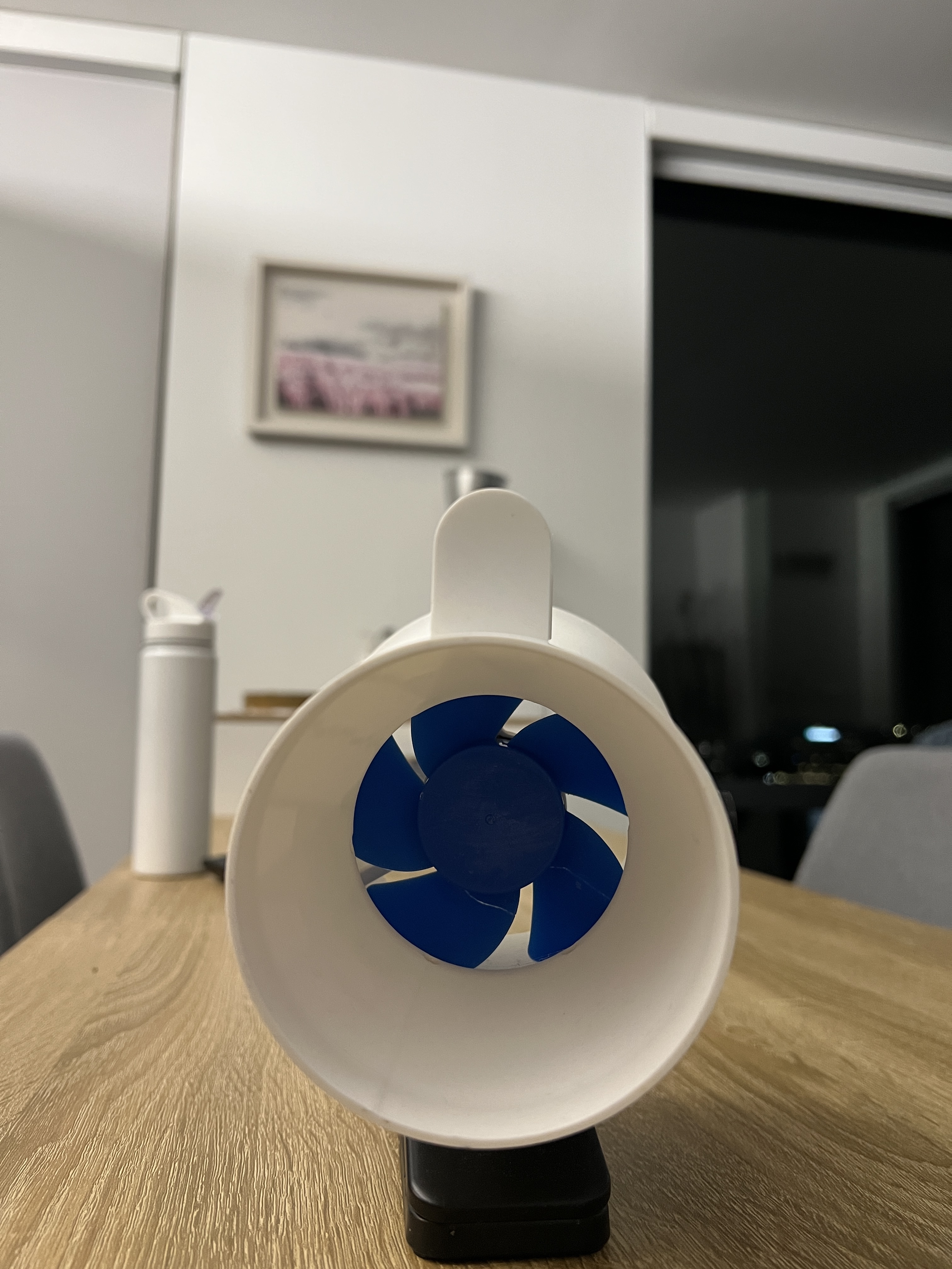
Designing the shroud was relatively straight-forward. I cut the cage off of the fan, measured the diameter of the fan blades, and designed the shroud with two main parameters in mind: 1 mm diametrical clearance to the fan tips, and a parabolic inlet area of 2x fan area. Just aft of the fan, there’s a converging-diverging nozzle section. The nozzle is not meant to drive the flow to sonic conditions, but to decrease the static pressure enough to use another feature: in the shroud body, I wanted to have angled orifices, positioned so that as the static pressure dropped in the nozzle, ambient air would get sucked in, forming an ejector. The benefit here would be increasing mass-flow through the fan. Last main design note: the fan centerbody was just a flat disk perpendicular to the flow direction. I glued on a parabolic nosecone here, again in the aim of keeping the main flow aligned as nicely as possible.
Parabolic inlets are the ideal shape for delivering clean (non-turbulent) air to a fan. When gas-turbine engines get tested on the ground, its these inlets (often called bellmouth inlets) that are used, since they’re an easy way to ensure that you’re delivering air to the engine as predictably as possible. They help make sure that air being sucked in isn’t separating from the inlet lip, and that it’s taken as low a pressure loss as possible.
Interfaces
All of the above sounds great for designing a very ‘aerodynamic’ flowpath. But I still had to think about the hardest parts of any design: interfacing with existing hardware. Making a high mass-flow, low-dP fan was kind of useless if I couldn’t make all this interface with the pan/tilt mechanism of the existing fan, as well as the clip. Also, in making this nice flowpath, I had gotten rid of one of the advantages of the as-is fan: convenient storage of the battery, control board, charging port, and button. The details aren’t worth getting into here, but it took a lot of caliper measurements and playing around with test-fits to get this part right, but I’m happy with how it turned out.
Integration and Final Product
Putting everythign together was honestly pretty easy. Once I settled on the final design, no reprints were necessary. In general, that’s how I like to design systems when it’s totally up to me: measure three times, marinade on the problem, measure again, think about the full lifecycle, and then send it. I recognize that that is almost never the case in startup engineering, where learnings and schedule risk need to get pushed as far to the left as possible. At the end of the day, the two approaches treat two different things as key constraints: for personal projects, I value waste minimization. Startups measure everything in time and runway. I can subjectively say that the fan feels like it performs a lot better, in that I get more focused air per power setting tht previously. However, I don’t have great analytical backing for this (see Improvements)
Improvements
I think the main thing I’d like to have done is take before-after pressure measurements, and use them to anchor/ validate CFD models. I’ve been super curious about working with OpenFOAM, and this might be a good candidate project. Without this sort of anchoring, any observations on the fan being ‘better’ (ie more mass flow per watt) are purely subjective.
Pictures